A forging that exits the die in perfect shape is still not a finished part. The grain structure is right, the material is sound, and the geometry is close — but close is not the same as correct for a transmission shaft running at 5,500 RPM or a differential cross shaft transmitting 2,800 Nm to the road. The gap between a forged blank and a part that meets engineering drawing tolerances is closed by forging machining, and the quality of that transition determines whether the mechanical advantages built into the forging actually survive into the finished component.
This is the step that procurement teams underestimate and engineers sometimes treat as a commodity. It isn’t either of those things.
Why Forged Blanks Cannot Go Straight into Service
The as-forged condition delivers dimensional tolerances that typically fall in the ±0.5 to ±1.6mm range per face, depending on part geometry and die condition — this is per IS 3469 and DIN 7526 for closed-die steel forgings. Flash trimming at the parting line leaves a shear face that needs cleanup. Draft angles of 5°–7° on external walls and 7°–10° on internal features, necessary for die release, leave tapered surfaces where the finished part needs parallel ones. Scale from the forging temperature — iron oxides forming at 1,100–1,250°C — sits embedded in the surface skin and must be removed before any precision cutting takes place. Shot blasting handles the scale, but the dimensional and geometric work falls entirely on forging machining.
There is also a subtler problem that doesn’t appear on visual inspection. The surface layer of a hot-forged component — typically 0.3–0.8mm deep depending on forging temperature and time in the die — has a decarburized zone where carbon has migrated out to the surface during heating. That decarburized skin is softer than the bulk material and must be fully removed in the machining sequence, because leaving it in place means the hardness measurement taken post-heat treatment represents a layer that won’t be there in service. For case-hardened gear blanks where surface carbon content drives final hardness, this isn’t a detail — it’s the difference between a 60 HRC tooth flank and a 52 HRC one.
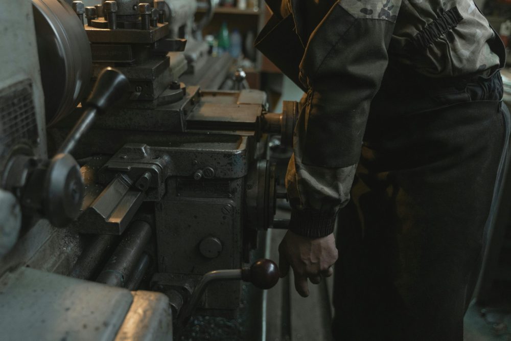
The Machining Sequence and What Each Stage Does
Forging machining for a structural component isn’t a single operation. It’s a sequenced process where each stage creates the datum reference or surface condition that the next stage requires, and skipping steps or reordering them compounds errors rather than correcting them.
Rough turning establishes the primary datums — the bore centreline and face references from which all subsequent dimensions originate. This cut removes the bulk of the forging allowance, typically 3–5mm depth of cut at feed rates of 0.3–0.5 mm/rev on medium carbon steel in the 200–250 HB range, with carbide inserts in CNMG or DNMG geometry at 150–200 m/min cutting speed. The goal is stock removal and datum establishment, not surface finish. Running these cuts on unhardened forgings is deliberate — hard turning after heat treatment removes far less material per pass and places significantly higher demands on tooling and machine rigidity.
Semi-finish turning and milling bring the part to within 0.3–0.5mm of final dimensions on non-critical faces and 0.1–0.2mm on features headed to grinding — this is where bore concentricity, shaft runout, and face perpendicular get established to IT9–IT10 grade. Keyways, cross-holes, and oil passages are also cut here, since they are far easier in the unhardened condition. A cross-hole through a shaft at 56 HRC consumes a solid carbide drill in a fraction of the cuts it would take at 25 HRC before heat treatment.
Heat treatment follows semi-finishing. For case-hardening steels like 20MnCr5, this means carburizing at 920°C for a duration calculated to achieve the specified effective case depth — typically 0.6–1.2mm for transmission components — followed by oil quench and low-temperature tempering at 160–180°C to relieve quench stresses without sacrificing surface hardness. Through-hardened parts in 4140 or 4340 go through quench and temper directly, targeting a core hardness range specified on the drawing, most commonly 28–34 HRC for shaft applications.
Finish grinding closes the tolerance to final dimensions. Cylindrical grinding on journal diameters brings bore and shaft tolerances to IT6 grade — ±0.008 to ±0.013mm on a 50mm diameter, for example. Surface grinding on thrust faces achieves flatness within 0.005mm and surface roughness in the Ra 0.4–0.8 µm range that bearing and seal interfaces require. Gear tooth grinding, where applied, takes the tooth profile from the hobbled or shaved condition to a DIN 5 or DIN 6 accuracy class, which for a module 3 gear means profile form error below 5 µm and pitch variation below 6 µm across the full tooth set.
Tolerances, Surface Finish, And Why Both Matter Independently
Tolerance and surface finish are related but distinct requirements, and confusing them causes specification errors that don’t appear until a component is assembled or already in service. A shaft journal ground to ±0.010mm dimensional tolerance but with Ra 1.6 µm surface finish will seat correctly in a bearing bore but will generate early fatigue pitting because the surface asperities are too tall relative to the EHL film thickness at operating speed and load. Conversely, a mirror-polished journal at Ra 0.2 µm but drifting 0.025mm off nominal creates a press-fit problem that no amount of surface quality compensates for. The forging machining sequence must control both independently — dimensional tolerance through machine calibration, work holding rigidity, and in-process gauging; surface finish through cutting speed, feed rate, tool nose radius, and the transition from rough to finish media, with CBN inserts for hard turning above 50 HRC and vitrified-bond aluminium oxide wheels for cylindrical grinding on case-hardened steels.
Grinding burn is a specific risk in the finish stage of forging machining that goes undetected until a field failure. When the wheel generates more heat than coolant can carry away, the surface layer re-austenitizes and self-quenches, creating a white layer of untampered martensite — typically 5–20 µm thick, hardness above 900 HV, and essentially no toughness. It doesn’t appear on Brinell checks or visual inspection; it breaks up in service as a crack initiation site. Nital etch inspection — swabbing with 2–4% nitric acid in ethanol and examining contrast — is the standard detection method and should be specified on any drawing that calls for ground surfaces on safety-critical components.
Measurement And Process Capability at Production Scale
A single part ground to tolerance in a job shop setting proves nothing about the process at 10,000 pieces per year. Forging machining at production scale requires Cpk data that confirms the process is not just capable of hitting tolerance but consistently centered within it. IATF 16949 and most OEM requirements set a minimum Cpk of 1.67 on special characteristics — safety-critical dimensions marked with a triangle or diamond on the drawing. That value means the process mean sits more than five standard deviations from the nearest specification limit, translating to fewer than 0.6 defective parts per million at steady state. For a shaft journal controlling bearing fit, that is a floor, not a target. Capability studies require a minimum of 30 consecutive pieces from production tooling under production conditions — not prototype runs, not operator-selected samples.
Sendura Forge Pvt. Ltd., certified to IATF 16949:2016 and ISO 9001:2015, runs integrated forging machining operations — from billet to finish-ground component — across a product range exceeding 700 part numbers serving customers including DANA, Mahindra, Eaton, WABCO, New Holland, TAFE, and Escorts, with in-house Gage R&R studies, nital etch protocols, and first-article inspection packages covering the full dimensional and metallurgical requirement set.
Tolerance Progression Through the Forging Machining Sequence
The figures represent standard expectations for medium carbon alloy steel components in the 50–150mm diameter range under production conditions.
| Machining Stage | Typical Dimensional Tolerance | Surface Roughness (Ra) | IT Grade Equivalent |
| As-Forged (pre-machining) | ±0.5 to ±1.6 mm | Ra 12.5–25 µm | IT14–IT16 |
| Rough Turning | ±0.2 to ±0.5 mm | Ra 6.3–12.5 µm | IT12–IT13 |
| Semi-Finish Turning | ±0.05 to ±0.2 mm | Ra 1.6–3.2 µm | IT9–IT10 |
| Finish Turning / Hard Turning | ±0.015 to ±0.05 mm | Ra 0.8–1.6 µm | IT7–IT8 |
| Cylindrical Grinding | ±0.005 to ±0.015 mm | Ra 0.2–0.8 µm | IT5–IT6 |
| Gear Tooth Grinding | Profile error < 5 µm | Ra 0.4–0.8 µm | DIN 5–DIN 6 |
Each stage in that table carries a different cost level, machine type, and quality control requirement. Specifying IT6 on a feature that only needs IT9 adds cycle time and grinding cost without improving function. Specifying IT9 on a bearing journal that requires IT6 guarantees assembly failures. The drawing callout and the machining stage must match, and that alignment is fixed in process planning — not recovered on the shop floor.
Conclusion
A forged blank without a controlled forging machining sequence is potential, not performance. The grain structure, fatigue resistance, and material density that forging delivers are irreplaceable starting conditions — but they mean nothing if the finished dimensions drift, the surface carries a grinding burn, or the case depth was left partially intact under a decarburized skin that never got fully removed.
The companies that understand forging machining as an integrated discipline — not as a separate subcontract function bolted onto the end of a forging order — are the ones whose parts consistently pass PPAP, hold Cpk at production volumes, and don’t generate warranty claims at year three. The ones that treat it as a commodity find out the hard way that tolerance on a drawing and tolerance in a delivered part are two entirely different things, and the gap between them lives in every process decision made between the forge press and the shipping dock.